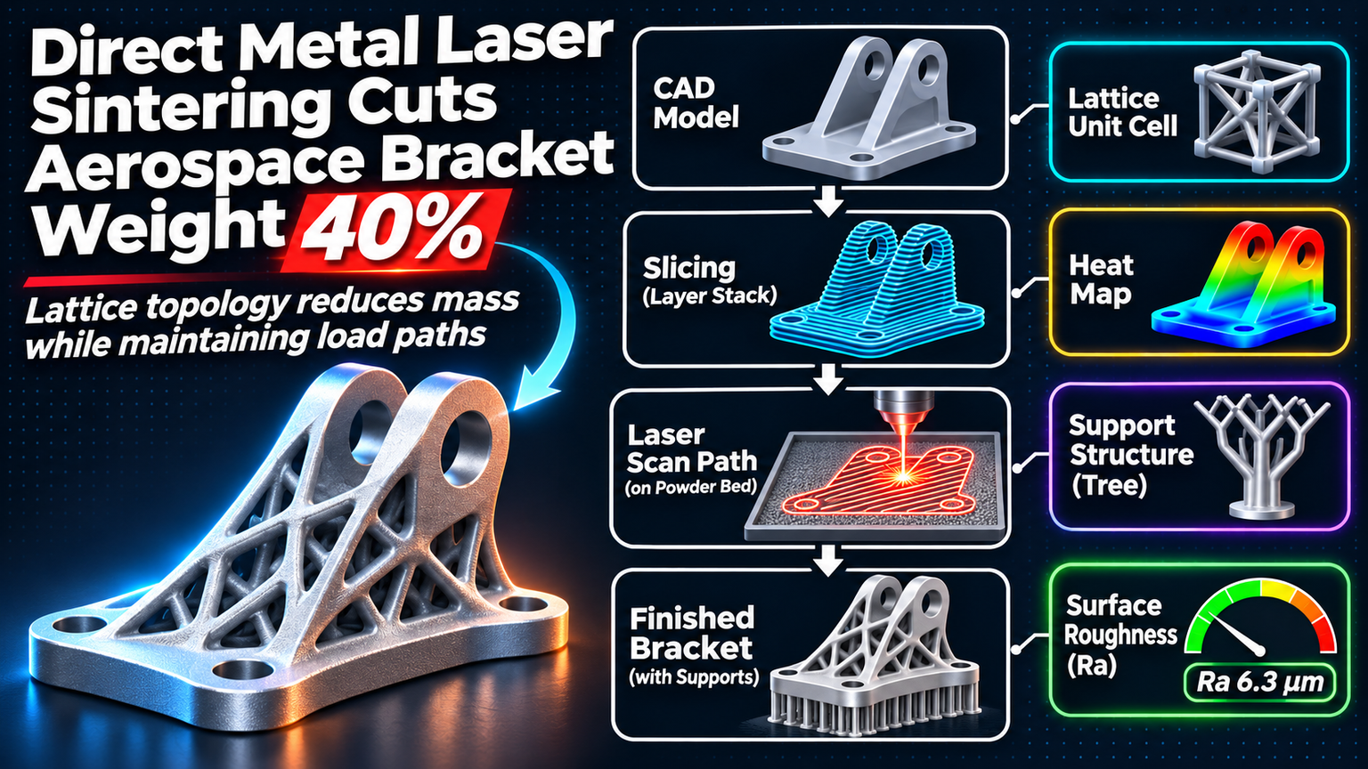
Aerospace engineers have chased weight savings for decades, but the last 40% is always the hardest. Direct Metal Laser Sintering (DMLS) just changed the math. By combining topology optimization with Inconel 718, one team dropped a flight-critical bracket from 2.3 kg to 1.38 kg without sacrificing a single Newton of load capacity.
The Starting Point: A Machined Brick
The original bracket was a CNC-machined block of Inconel 718, designed with generous safety factors and uniform wall thickness. It survived vibration, thermal cycling, and 9g loads. It also carried 920 grams of dead weight — material that existed only because subtractive manufacturing couldn't carve it away without weakening the part.
Topology Optimization: Letting Math Drive Geometry
The redesign started in nTopology. Load cases included max thrust, lateral maneuver, thermal gradient, and emergency shutdown. The optimizer ran 120 iterations, stripping material from low-stress zones while maintaining a 1.5 safety factor on yield. The result looked organic — lattice webs, tapered flanges, hollow cores — and weighed 1.45 kg on screen.
💡
TipRun optimization with manufacturing constraints active. Minimum wall thickness (0.8 mm for DMLS), overhang angle (45°), and drain hole placement must be baked in, not patched later.
Build Orientation: The Hidden Variable
Orientation decides surface quality, support volume, and residual stress. The team tested three angles in simulation: 0°, 30°, and 45° from vertical. At 0°, the lattice webs fused to the build plate but trapped powder in closed cells. At 45°, supports ballooned to 38% of part volume. The sweet spot was 30° — self-supporting angles on critical surfaces, minimal trapped powder, and support volume under 12%.
| Orientation | Support Volume | Surface Roughness (Ra) | Build Time | Post-Process Hours |
|---|---|---|---|---|
| 0° (flat) | 8% | 12 µm | 42 hrs | 18 hrs |
| 30° (optimal) | 12% | 8 µm | 38 hrs | 9 hrs |
| 45° | 38% | 6 µm | 55 hrs | 24 hrs |
Inconel 718: Process Parameters That Matter
Standard DMLS parameters for Inconel 718 (30 µm layer, 200 W laser, 1000 mm/s scan speed) produced micro-cracking in thin lattice struts. The fix: reduced power (160 W), slower scan (800 mm/s), and a 60 µm hatch spacing. This lowered thermal gradient enough to prevent solidification cracking while keeping density above 99.95%. Hot isostatic pressing (HIP) at 1120°C/100 MPa/4 hrs closed the remaining pores.
Support Removal: The Labor Trap
Supports on Inconel 718 don't break away clean. The 30° orientation kept supports to internal channels and lattice nodes. The team used a two-step removal: wire EDM for internal supports (0.1 mm wire, 2 mm/min feed) followed by abrasive flow machining for surface finish. Total post-process time dropped from 24 hours (45° build) to 9 hours.
"The geometry looked impossible on screen. Holding the finished part — feeling how light it was — that's when the CAD model became real.
— Lead Structures Engineer, confidential aerospace program
Validation: Test Like You Fly
Three brackets went to test. Static load to 150% limit load — no permanent deformation. Vibration sweep 20-2000 Hz at 14.1 g RMS — no resonance shift vs. FEA. Thermal cycle -55°C to 315°C, 50 cycles — dimensional stability within 0.02 mm. CT scanning confirmed zero internal defects >50 µm. All three passed.
✦
Your Next Bracket Starts Here
Weight savings this large don't come from printing the same geometry in metal. They come from redesigning for the process. Start with these steps:
ℹ️
Note1. Export your current bracket's load cases and boundary conditions. 2. Run topology optimization with DMLS constraints (min wall, overhang, drain holes). 3. Simulate three build orientations for support volume and thermal stress. 4. Print coupons at your chosen parameters — validate density and microstructure before the full part. 5. Plan post-process removal before you hit 'build'.