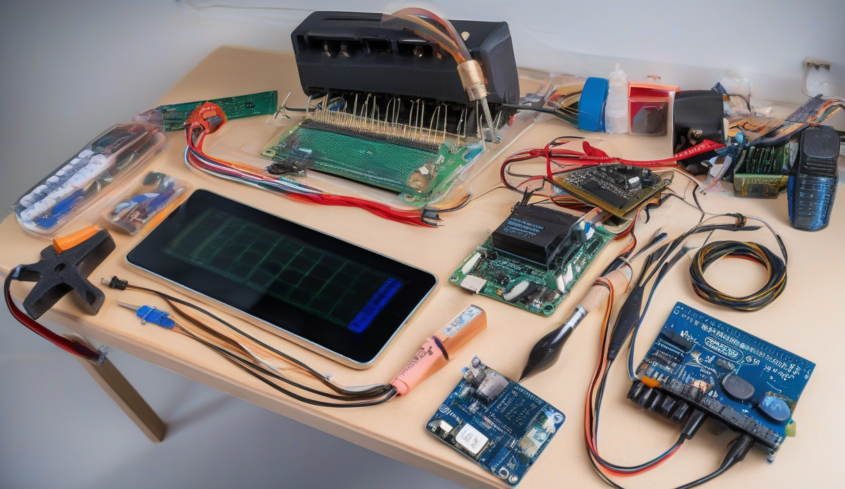
You don't learn electronics by watching videos. You learn by burning a fingertip on a soldering iron, debugging a floating pin at 2 AM, and finally hearing that speaker crackle to life. The gap between schematic and working device is where actual engineering happens.
Start With the Right Iron
A $15 pencil iron from a big-box store will teach you frustration. Spend $60-80 on a temperature-controlled station (Hakko FX-888D or Pinecil v2). Add 63/37 leaded solder (0.6mm), flux pen, brass sponge, and helping hands. Your joints will be shiny, not cold.
💡
TipLead-free solder requires higher temps and flows poorly. For learning, 63/37 Sn/Pb is forgiving. Wash hands after.
Breadboard First, PCB Later
Prototype on a quality breadboard (not the $3 transparent ones with loose clips). Validate every subcircuit: power regulation, sensor interface, comms module. Only then commit to copper. I use JLCPCB for 2-layer boards — $2 for 5 pieces, 4-day turnaround.
ESP32: The Swiss Army Knife
For 2026 projects, the ESP32-S3 (dual-core, 240 MHz, native USB, 512 KB SRAM) replaces Arduino Uno as the default starter brain. Wi-Fi, BLE, touch, ADC, DAC, camera interface — all for $8. Program it in Arduino IDE, PlatformIO, or MicroPython.
| Module | Use Case | Approx Cost |
|---|---|---|
| ESP32-S3 DevKitC-1 | General prototyping | $8 |
| ESP32-CAM | Computer vision | $10 |
| ESP32-S3-Touch-LCD | GUI appliances | $18 |
| XIAO ESP32S3 | Wearables, tight spaces | $9 |
Power Design Separates Toys From Tools
Don't power servos from the ESP32's 3.3V regulator. Use a buck converter (MP1584 or LM2596S) for 5V/3A rails, and a dedicated LDO (AP2112K-3.3) for the MCU. Add 470 µF electrolytic + 0.1 µF ceramic at each supply entry. Measure ripple with a scope before connecting logic.
"A circuit that works on the bench but fails in the field is a circuit that was never finished.
— Bob Pease
Soldering Basics Checklist
1. Clean pads with isopropyl. 2. Flux every joint. 3. Heat pad and lead simultaneously 2-3 seconds. 4. Feed solder to joint, not iron tip. 5. Remove solder, then iron. 6. Joint should be concave, shiny, volcano-shaped. 7. Inspect under 10x loupe. 8. Flux residue? Clean with 99% IPA and brush.
⚠️
WarningCold joints look dull and cracked. They pass continuity but fail under vibration or thermal cycling. Reflow them.
Debug Like You Mean It
Serial.print() is not a debugger. Get a logic analyzer (Saleae Logic 8 or $15 CY7C68013A clone) for I2C/SPI/UART decoding. A 2-channel 100 MHz scope (Rigol DHO802) catches glitches analyzers miss. Learn to trigger on runt pulses and setup/hold violations.
✦
Your Next Build Starts Tonight
Pick one project: a Wi-Fi environment logger (ESP32 + BME280 + MQTT), a macro keypad (XIAO + Cherry MX + 3D printed case), or a solar-powered LoRa tracker. Order parts today. Breadboard it this week. Design the PCB next weekend. Order boards Monday. Assemble when they arrive. Ship firmware. Repeat. That's the cycle. The only difference between a maker and an engineer is how many times you've gone around.